

Ultimate Guide to 6th Order Bandpass Box Design for Superior Sound
Posted by Jacob Morris on Jan 1st 2026
6th Order Bandpass Box Design: Step-by-Step Guide to Build, Test, and Tune
Building a 6th order bandpass box requires careful planning, precise measurements, and respect for physics. The short answer is this: check your subwoofer specs, model your volumes and tunings in software, build an airtight shell, install adjustable ports, measure everything, and protect your subs with proper crossovers. Skip any of these steps and you risk an expensive lesson.
This guide walks you through the entire process—from selecting the right driver to fine-tuning your enclosure in the vehicle. Whether you want extreme SPL for competition or a punchy daily driver, understanding 6th order bandpass box design puts you ahead of builders who rely on guesswork and forum myths. Starting with a clear idea or benchmark for your system design and tuning strategy is crucial for achieving optimal results.
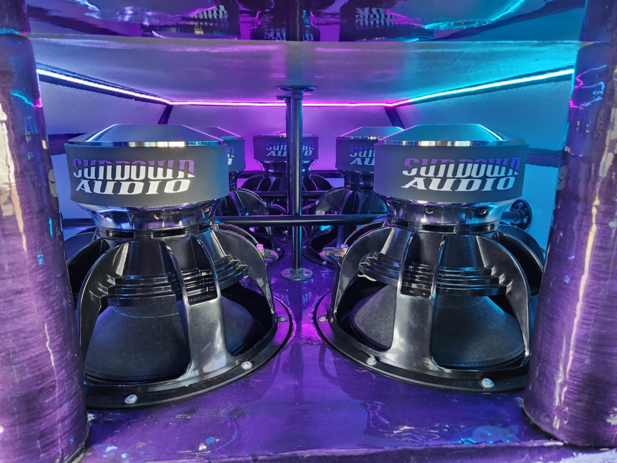
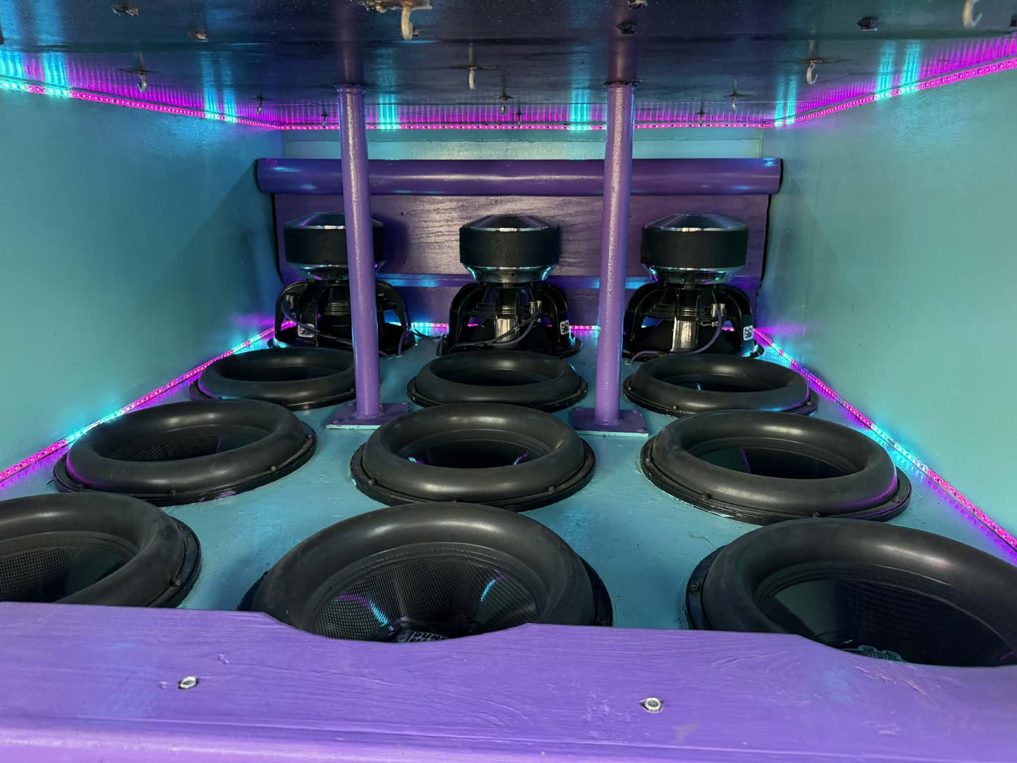
A 6th order bandpass enclosure uses two ported chambers with the woofer mounted entirely inside the box. All sound output exits through the ports, creating a sharply defined passband with steep roll-offs on both sides—typically 36 dB per octave. This design offers tremendous efficiency within its target frequency range but demands careful execution.
There are actually multiple types of 6th order designs: quasi series-tuned, true series, and parallel configurations. Each behaves differently in terms of response curve, bandwidth, and usability. A later section will preview these variations and link to a detailed comparison article covering different types of 6th order bandpass boxes.
Step 1: Check Your Subwoofer Specifications
Before you cut a single piece of wood, you need to know whether your subwoofer is even a candidate for a 6th order. The Thiele-Small parameters tell you everything. Forcing the wrong driver into this enclosure type leads to peaky one-note bass, dangerous unloading, or both.
Key Parameters to Evaluate
Fs ÷ Qes Ratio
|
Ratio Result |
Recommended Enclosure |
|---|---|
|
Below 45 |
4th order bandpass or ported |
|
Above 50 |
6th order bandpass candidate |
Qts Value – Learn more about how the Qts value fits into the basics of Thiele/Small (T/S) parameters and speaker performance.
|
Qts Range |
Suitability |
|---|---|
|
Below 0.45 |
Ideal for 6th order |
|
0.45–0.55 |
May work, requires careful modeling |
|
Above 0.55 |
Usually favors sealed or 4th order |
Worked Example
Consider a sub with Fs of 32 Hz and Qes of 0.55:
-
Fs ÷ Qes = 32 ÷ 0.55 ≈ 58
-
Result above 50 suggests 6th order potential
Now check Qts. If this sub has a Qts of 0.40, it fits both criteria well. A Qts of 0.60 would raise concerns.
Real-world subs from brands like Sundown, Incriminator, and Crossfire often publish detailed specs. For SPL builds, drivers like the Wolfram Audio Mercury HGv2 12 (Qts around 0.36) have been used in successful 6th order competition vehicles. Daily builds might use more moderate drivers with Qts around 0.38–0.42.
These are guidelines, not absolute rules. Every design must be modeled in software like WinISD, Hornresp, or BassBox before construction begins.
Avoid using “no-spec” subs from unknown brands unless you can measure the T/S parameters yourself with a DATS or similar tool. Complex enclosures amplify any mismatch between the driver and the design.
Step 2: Define Your Goals and Target Passband
Your goals shape everything—volume ratios, port tunings, construction priorities. A competition SPL build targeting 160+ dB has completely different requirements than a SQL daily driver meant to blend smoothly with your mids.
Typical Use Cases
-
SPL Competition (dB Drag, MECA): Narrow, extremely loud passband. Goal is maximum cabin scores like 156–162 dB at a specific frequency.
-
Demo Vehicle / Street Demo: Wide but aggressive bandwidth for “hair tricks” and demo nights. Impressive on various tracks without being a true single-frequency monster.
-
SQL Daily Driver: Smoother response that blends with speakers and midbass. Strong low end without punishing your ears on every song.
Concrete Tuning Pairs
|
Build Type |
Rear Chamber Tune |
Front Chamber Tune |
|---|---|---|
|
SPL |
~25 Hz |
~50 Hz |
|
SQL |
~30 Hz |
~60 Hz |
|
Daily |
~28 Hz |
~52 Hz |
Cabin Gain Matters
Many SUVs and sedans naturally boost frequencies 3–8 Hz below your tuning due to cabin gain. A 30 Hz rear tune might actually peak hardest around 25–27 Hz on the dash. This can work in your favor for SPL, but it also means you should model with your vehicle in mind, not just free-air calculations.
Musical Style Considerations
-
Rap, trap, rebassed remixes: Favor lower rear tunings (26–30 Hz) for deep, sustained low notes.
-
Rock and pop: Slightly higher front tuning (40–55 Hz) adds punch and attack.
Make these decisions before any size or port math. Changing goals mid-project means redesigning from scratch.
Step 3: Choose Rear and Front Chamber Volumes
A 6th order has two independent ported chambers. The rear chamber handles low bass and sits behind the woofer. The front chamber shapes the upper bass and controls bandwidth. Getting this ratio wrong creates problems that no amount of tuning can fix.
The Golden Ratio
For most car audio 6th order builds, the rear chamber should be approximately 1 to 2 times larger than the front chamber. This balance prevents the front chamber from dominating and creating a peaky, narrow response.
Example Starting Points
|
Configuration |
Rear Chamber (Net) |
Front Chamber (Net) |
|---|---|---|
|
Single 12” daily |
1.8-2.2 ft³ |
1.8–2.2 ft³ / 3.6–4.4 ft³ |
|
Pair of 15s demo (SUV) |
5.8-7ft³ |
5.8-7ft³ / 11.6–14 ft³ |
|
Single 15” SQL |
3-4 ft³ |
3-4 ft³ / 6-8 ft³ |
Remember that “net volume” means after subtracting woofer displacement, port displacement, and internal bracing. A box that measures 4 ft³ outside might only provide 3.2 ft³ net.
What Happens When You Invert the Ratio
Making the front chamber much smaller than the rear typically creates a very peaky, one-note system. The response becomes narrow and honky rather than wide and powerful.
Competition builds in large SUVs sometimes use 80–120+ ft³ gross enclosures. A late-90s Suburban-style build might dedicate 40 ft³ or more to chambers housing multiple 15s or 18s. For those projects, the scale is extreme, but the volume ratio principles remain the same.
Start with volumes slightly larger than your modeling suggests. You can always add internal blocks to reduce volume and fine-tune. Rebuilding a too-small enclosure is far more painful.
Step 4: Port Design, Tuning, and Air Velocity Control
Each chamber gets its own port, and both must be designed like separate vented boxes. This is where many builders go wrong—under-porting even one chamber causes compression, chuffing, and heat buildup that kills performance and potentially your subs.
Tuning Assignments
|
Chamber |
Typical Tuning Range |
Purpose |
|---|---|---|
|
Rear |
20–25 Hz |
Low bass foundation |
|
Front |
40–50 Hz |
Upper bass and bandwidth |
Using WinISD for Port Calculations
-
Enter your net volumes for each chamber.
-
Input desired tuning frequencies.
-
Adjust port length until you hit target tunings.
-
Check port air velocity—aim for under 20–25 m/s at full power.
Under-porting leads to velocities exceeding 25–35 m/s, which creates audible chuffing and whistling.
Port Type Choices
|
Port Style |
Pros |
Cons |
|---|---|---|
|
Slot port |
Can be built into box structure, efficient use of space |
Harder to adjust length after construction |
|
Round aeroport |
Easy to swap lengths, clean airflow |
Takes up more internal volume |
|
Adjustable aeroport |
Allows tuning changes without rebuilding |
Requires planning for access |
Removable or length-adjustable aeroports make life much easier. Competition builders often spend months trimming ports in half-inch increments to gain 1–2 dB.
Reduce Port Noise
Round over port entries and exits with a 1/2” to 1” radius using a router bit. This simple step dramatically reduces chuffing and whistling at high output levels. Many pro audio and Panaray-style builds treat port smoothing as mandatory.
Model with your vehicle cabin in mind. A box that looks perfect in WinISD might sound wrong in your specific car due to cabin resonances and gain patterns.
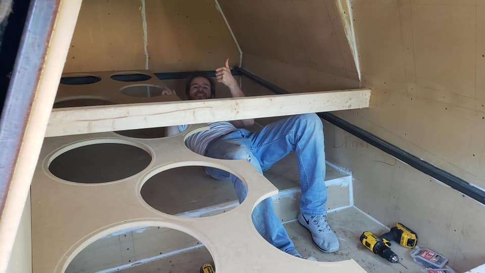
Step 5: Build the Shell First (Strong, Airtight Construction)
Structural integrity is the foundation of predictable 6th order behavior. Under several kilowatts of power, a flexing panel becomes an energy sink that robs output and can even change your tuning. Build it right the first time.
Build Process:
-
Measure and mark all panels.
-
Cut all pieces.
-
Use a jig with your router or jigsaw to cut perfect round holes for the subwoofer and ports. This ensures clean, repeatable cuts and a precise fit.
-
Dry fit panels to check alignment. (if possible)
-
Glue and clamp panels, then screw or nail for extra strength.
-
Seal all internal joints with caulk to prevent air leaks.
Practical Tips:
-
Always pre-drill for screws to avoid splitting MDF or plywood.
-
Carefully mark and cut each hole for ports and subwoofers. Clean edges are important for optimal sound quality and proper fit.
-
Use a jig for accurate and repeatable hole cutting, especially for round or complex shapes.
-
Double-check all measurements before making cuts.
Recommended Materials
-
3/4” MDF or 3/4” Baltic birch plywood for all panels
-
Double baffle on the woofer mounting side
-
Kerfing or stacked baffles where massive port openings weaken panels
-
Heavy internal bracing with window braces, dowels, or steel angle iron
Build Process
-
Create a detailed cut list. Label every panel: TOP, BOTTOM, REAR, FRONT-LOW, FRONT-HIGH, DIVIDER, etc.
-
Cut all pieces. Use a table saw or circular saw with a straightedge guide for accuracy.
-
Dry-fit the shell without ports to confirm alignment. Mark any adjustments with a pencil.
-
Glue and fasten. Use wood glue generously on all seams. Screw or clamp panels tightly.
-
Add bracing. Space braces every 12 inches on large flat panels to prevent oil-canning at high SPL.
At this stage, the shell should be fully sealed and mechanically solid before cutting in or installing ports.
Practical Tips
-
Pre-drill for screws to prevent MDF splitting
-
Use construction adhesive like PL 3x, Liquid Nails, or thick wood glue fillets inside all seams
-
Consider access panels that are bolted and gasketed for service and retuning
-
Test for airtightness by sealing all holes and checking for leaks with incense smoke / smoker.
Many bassheads use fiberglass resin after construction adhesive to create a strong, airtight seal and reinforce the enclosure, preventing air leaks and reducing flex under high power loads.
A single small air leak or can greatly affect your tuning and ruin the entire design. This step requires patience.
Step 6: Install and Adjust Ports (Tuning in Wood, Not Just Software)
Real-world tuning rarely matches software modeling perfectly. Factors like bracing, woofer placement, and port position all affect the final result. Build your ports to be adjustable from the start.
Installation Process
-
Start with ports slightly longer than modeled. Longer ports tune lower, giving you room to trim up.
-
Play test tones (sine waves at your target frequencies).
-
Measure impedance or SPL to verify actual tuning frequencies.
-
Trim ports gradually in 1/2” to 1” increments until desired tunings are reached.
Make Ports Adjustable
Removable aeroports or bolt-in port panels with gaskets allow you to swap lengths or areas without tearing apart the entire enclosure. Many competition vehicles go through multiple port configurations over a season.
Some builders in a Chevy Suburban or a Jeep Grand Cherokee SPL builds spent months trimming and changing port setups to gain just 1–2 dB at their target frequency. That level of fine-tuning separates good scores from great ones.
Important Warning
Changing port length in one chamber affects overall response and peak location. Only change one chamber at a time and re-measure before making additional adjustments.
If you shorten the front port and the rear port in the same session, you won’t know which change helped or hurt. Document everything.
How to Tune a Port in Your 6th Order Bandpass Box
Tuning the ports correctly is crucial to achieving the desired frequency response and maximizing bass performance. Here are some practical tips on how port dimensions affect tuning:
-
Adding Length to a Port: Increasing the length of a port lowers its tuning frequency. A longer port makes the air column resonate at a lower pitch, which helps extend the bass response deeper.
-
Shrinking a Loading Wall: Reducing the size of the loading wall (the partition inside the enclosure that defines port dimensions) effectively decreases the port's cross-sectional area. This also lowers the tuning frequency, allowing the enclosure to play lower notes.
-
Making the Port More Open: Increasing the port’s cross-sectional area or diameter raises the tuning frequency. Shifting the resonance higher and tightening the bass response.
-
Port Diameter and Air Velocity: Keep in mind that making a port too narrow or too long can increase air velocity, causing chuffing noise and reduced efficiency. Aim for a balance that maintains port velocity under 20–25 m/s at full power.
-
Adjustable Ports: Designing ports to be adjustable (removable or with extendable tubes) allows fine-tuning after initial testing, helping you dial in the perfect tuning based on real measurements rather than just software predictions.
By understanding these relationships, you can experiment with port length and cross-sectional area to tailor your enclosure’s bass characteristics precisely to your needs.
Step 7: Test, Measure, and Fine-Tune the Enclosure
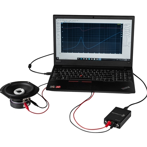
Measurement separates lucky builds from predictable, repeatable designs. You can guess your way to a working enclosure, but you’ll never know why it works—or how to fix it when something goes wrong.
Essential Measurements
Impedance Sweeps
Use a DATS or DIY impedance test rig to locate the two main peaks. These peaks should appear near your rear and front tuning frequencies. If they’re off, adjust port lengths accordingly.
SPL Testing
Measure on the dash and at the headrest using a calibrated meter (Term-Lab, SPL-Lab, SSA, etc.). This tells you where your system actually peaks in the vehicle, not just what modeling predicted.
Frequency Sweeps
Run sweeps from 20–80 Hz to find dead spots, sharp peaks, and cabin resonances. Pink noise and sine sweeps both provide useful data.
Target Results by Build Type
|
Build Type |
Frequency Response Goal |
|---|---|
|
SPL competition |
Very strong peak around 35–60 Hz, 160+ dB outlaw scores |
|
SQL daily |
Smoother plot from ~25–55 Hz, moderate peaking |
|
Demo vehicle |
Wide passband with impressive output across 18–50 Hz |
Tuning with DSP and EQ
Basic EQ and crossover tuning in your head unit or DSP can smooth cabin response without flattening the box’s natural efficiency. A small cut at a room mode or a bit of boost in a dead spot makes music sound more balanced.
Test with Real Music
Use tracks with known strong content in your bandwidth. Bass test tracks, decaf remixes, and songs you know well help confirm that the system behaves as measurements predict.
Document all changes—port length, volume adjustments, amplifier gain settings—with dates. This lets you revert to the best-performing configuration if future changes make things worse.
Step 8: Protect Your Subwoofers and Electrical System
6th order enclosures unload violently outside their passband. Below the rear tuning, cone excursion can spike to 2–3 times Xmax. Above the front tuning, the driver also loses acoustic loading. You will not hear a woofer failing until it is too late.
Electronic Protections (Non-Negotiable)
|
Filter Type |
Setting Example |
Purpose |
|---|---|---|
|
High-pass (subsonic) |
24 dB/oct at 24–28 Hz (for 30 Hz rear tune) |
Prevents dangerous low-frequency excursion |
|
Low-pass |
24 dB/oct at 70–80 Hz (for 60 Hz front tune) |
Blocks out-of-band content above passband |
Fusing and Electrical System
Proper fusing at the amplifier, under the hood, and at any auxiliary banks (AGM, LTO, XS Power Superbanks) prevents electrical fires. Match fuse ratings to wire gauge and amplifier requirements.
Electrical System Sizing
|
Power Level |
Minimum Requirements |
|---|---|
|
2–4 kW |
A run of 1/0 OFC, 200+ amp alternator |
|
5–10 kW |
Multiple 1/0 or 2/0 runs, 250–300+ amp alternator |
|
10–20+ kW |
High-output alternator (300+ amp) + lithium batteries / battery bank |
Why Protection Matters More in 6th Orders
Unlike sealed or ported boxes, 6th orders hide mechanical distress. The woofer is inside the enclosure, and you cannot see or hear it bottoming out until coil damage is done. Treat protection filters as mandatory, not optional.
For home or pro audio builds without active crossover control, consider adding an inductor (passive low-pass) in the signal path.
Common Mistakes and How to Avoid Them
Many failed 6th order attempts trace back to a handful of repeatable issues. Knowing these ahead of time saves money, time, and frustration.
Major Mistakes
|
Mistake |
Consequence |
|---|---|
|
Guessing volumes instead of modeling |
Tuning ends up 10+ Hz off target |
|
Under-porting either chamber |
Compression, port noise, heat buildup |
|
Ignoring T/S specs |
Driver unsuited for 6th order response |
|
Skipping bracing |
Box flex at high SPL, lost output |
|
No electronic crossovers |
Dangerous out-of-band excursion, blown subs |
|
Rushing construction |
Poor seals, air leaks, mis-aligned baffles |
Real-World Scenario
A builder converts a 4th order to a 6th by adding a second port to the previously sealed chamber without retuning either port. The result is worse performance than the original—peaky, narrow, and with port noise at moderate power. The front chamber volume was too large relative to rear, and neither port was recalculated.
The fix required tearing apart the added chamber, resizing it, and recalculating both port lengths from scratch. Time spent: three weekends. Money lost: significant. If you’re curious about what kind of subwoofer might benefit from this level of enclosure tuning.
Take time modeling and testing instead of chasing quick numbers or “magic” ratios copied from forums. Your specific driver, vehicle, and goals require specific calculations.
Types of 6th Order Bandpass Enclosures (Preview for Internal Link)
There is more than one way to build a 6th order, and different types behave very differently. Understanding these variations helps you choose the right form for your goals.
Key Variations
|
Type |
Description |
Common Use |
|---|---|---|
|
Series tuned (quasi 6th) |
Rear and front chambers in acoustic series |
Most common in modern car audio, good balance of output and bandwidth |
|
True 6th order |
Both chambers fully bandpass-shaping the driver |
Pro audio subs, specialty applications |
|
Parallel 6th order |
One chamber as loading, one as output shaper |
Hybrid designs for specific response curves |
Why Series Tuned Dominates Car Audio
Series tuned (quasi) 6th order designs balance output, control, and real-world usability better than full BP6 builds. They offer 10–20% smaller footprints and better phase coherence, trading only 2–4 dB peak output for a flatter 10–15 Hz bandwidth.
For daily drivers and demo vehicles, quasi designs are the practical choice. True 6th orders still appear in dedicated SPL builds where every fraction of a dB matters.
A separate article will cover:
-
Detailed differences in response curves
-
When to choose each type
-
Example box plans and vehicle applications
Look for our guide on different types of 6th order bandpass boxes to explore these variations in depth.
Real-World Examples: From Compact DIY to Extreme SUV Builds
6th orders scale from small 12” PA subs to massive multi-18” SUV installations. The principles remain consistent even as the numbers get extreme.
Compact 12” Home or Small-Venue Build
A builder wanted a punchy subwoofer box for a small PA setup with a passband roughly 50–140 Hz. Using 3/4” MDF, basic hand tools, and a moderate 400W amplifier, the project came together over two weekends.
The rear chamber measured about 2.5 ft³ net with a 6” round aeroport tuned to 45 Hz. The front chamber ran 0.9 ft³ with a shorter port tuned to 85 Hz. The result blended well with 12” tops, adding weight without muddiness.
Total material cost ran under $150. The enclosure was portable, fit in a hatchback, and handled moderate outdoor events without strain. Music sounded full and punchy, with the steep roll-off keeping the sub out of the way of vocals and instruments.
Large SUV SPL Build
At the opposite extreme, an early-2000s Suburban-style build packed six 15” subs into a multi-chamber enclosure consuming roughly 100 ft³ gross. The vehicle featured:
-
Six runs of 1/0 OFC from the battery bank
-
Dual 370-amp high-output alternators
-
Multi lithium batteries for true power handling
-
Total system power exceeding 15 kW
The enclosure tuned rear chambers around 28 Hz and front around 55 Hz, targeting peak output in the low 40s where cabin gain added another 10+ dB. Competition scores exceeded 160 dB outlaw with doors open, and 156+ sealed on the dash.
This project took over a year of refinement—port trimming, electrical upgrades, vehicle reinforcement (welding seams, deadening). The structure of the vehicle itself became part of the resonant system.
Contrasting Priorities
|
Aspect |
Compact Build |
SUV SPL Build |
|---|---|---|
|
Primary goal |
Musicality, portability |
Maximum SPL in narrow band |
|
Power handling |
500–2000 W |
15,000+ W |
|
Fine-tuning time |
Days |
Months to years |
|
Vehicle modifications |
None |
Extensive |
Both builds followed the same design principles. Scale and dedication differed dramatically.
Tools, Materials, and Workspace Setup
The right tools make a complex enclosure like a 6th order far more achievable for DIY builders. You don’t need a professional shop, but you do need reliable equipment and a safe workspace.
Core Tools
-
Table saw or circular saw with straightedge guide
-
Jigsaw for curves and port cutouts
-
Handheld router with round-over and flush-trim bits
-
Cordless drill/driver
-
Clamps (many of them—you cannot have too many)
-
Measuring tape, square, and pencil for marking
Typical Materials
|
Item |
Common Specification |
|---|---|
|
Panel material |
3/4” MDF or Baltic birch plywood (4’x8’ sheets) |
|
Adhesive |
Wood glue and construction adhesive |
|
Fasteners |
2” wood screws, pre-drill to prevent splitting |
|
Wiring |
12 AWG+ speaker wire |
|
Terminals |
Terminal cups or binding posts |
|
Sealing |
Gasket tape, silicone caulk |
Optional But Helpful
-
Soldering iron for secure wire connections
-
Paint, carpet, or bedliner for finishing
-
Handles for portability
-
Grill material for port protection
-
Measurement microphone and RTA software for tuning
Safety Notes
Dust collection or at minimum a shop vacuum keeps MDF particles manageable. Wear a dust mask rated for fine particulates—MDF dust is not cool to breathe. Eye protection during cutting and routing is mandatory. Hearing protection during testing protects your most valuable asset.
Finishing, Installation, and Long-Term Reliability
Finishing work protects the enclosure and improves appearance, especially for show or demo vehicles. An excellent build deserves an excellent finish.
Finishing Options
|
Method |
Pros |
Cons |
|---|---|---|
|
Carpet |
Traditional look, hides minor flaws |
Can trap moisture if not sealed underneath |
|
Paint |
Smooth, professional, many color options |
Shows imperfections, requires prep work |
|
Bedliner |
Extremely durable, seals MDF |
Heavy, textured appearance |
|
Vinyl wrap |
Clean look, removable |
Requires skill to apply without bubbles |
Seal all screw holes, seams, and access panels with caulk or gasket. Every potential air leak needs attention.
Long-Term Mounting
Use T-nuts or hurricane nuts for woofer mounting. Standard wood screws strip out after repeated removal. Add handles or anchor points where the box will be moved or secured in the vehicle.
Maintenance Checklist
-
Periodic inspection: Check for leaks, loose fasteners, and cracked joints
-
Electrical connections: Re-check after hard demo sessions or competitions
-
Thermal monitoring: Watch for voice coil smell or excessive heat; back off if protection filters are being pushed
-
Fastener tightening: Vibration loosens hardware over time
A 6th order built and maintained correctly will deliver reliable performance season after season.
Final Thoughts: When a 6th Order Bandpass Is Worth the Effort
A correctly designed 6th order can deliver extreme output, wide usable bandwidth, and excellent cone control. It can also become an expensive lesson if rushed or poorly executed. The design requires respect and careful planning at every stage.
Ideal Candidates for 6th Order Builds
-
Dedicated demo vehicles where bass impact is the priority
-
SPL competitors chasing every fraction of a dB
-
Experienced DIYers willing to measure, rebuild, and fine-tune
If you’re new to enclosure building, start with sealed or standard ported boxes first. Graduate to 4th order bandpass once you understand modeling and measurements. Then tackle 6th order with the confidence that comes from knowing what happens when something goes wrong.
Most modern builders lean toward quasi series-tuned 6th orders because they balance real-world usability and output better than older “full” 6th order designs. The bit lower peak output trades for a noticeably bigger usable bandwidth.
Next Steps
Explore our detailed guide on different types of 6th order bandpass boxes to understand which configuration matches your goals. Each type has distinct advantages depending on your vehicle, subs, and priorities.
At Amped Up Car Audio, we carry the subwoofers, amplifiers, wiring, electrical upgrades, and accessories needed to support serious 6th order builds. Whether you’re planning a compact daily project or a full-scale SPL monster, the right components make the difference.
Build smart. Build loud. Build it once.
Written by Jacob Morris
Audio Expert, Co-Owner of Amped Up Car Audio